Lab 3 - Sensors:
In this lab I set up the sensors that will be used on the robot. These include a Time of Flight Sensor for proximity detection and an IMU for motion detection.
Wiring:
Wiring was a challenge because of limited access to good soldering equipment. Eventually I got the below wiring setup.

Time of Flight Sensors:
ToF Sensor Address:
I was unable to run the Wire example because I had already wired up both ToF sensors and the IMU, but my understanding from the documentation is that I will get an address of 0x29 because the sensor address of 0x52 gets right shifted by one bit.
ToF Mode Performance:
Short distance mode is resistant to ambient factors while long distance mode can sense objects from a further distance. Medium distance mode splits the difference in both aspects. For our purpose long is likely the best option because we need
to view far objects for quick localization.
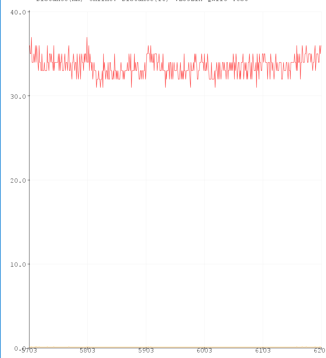
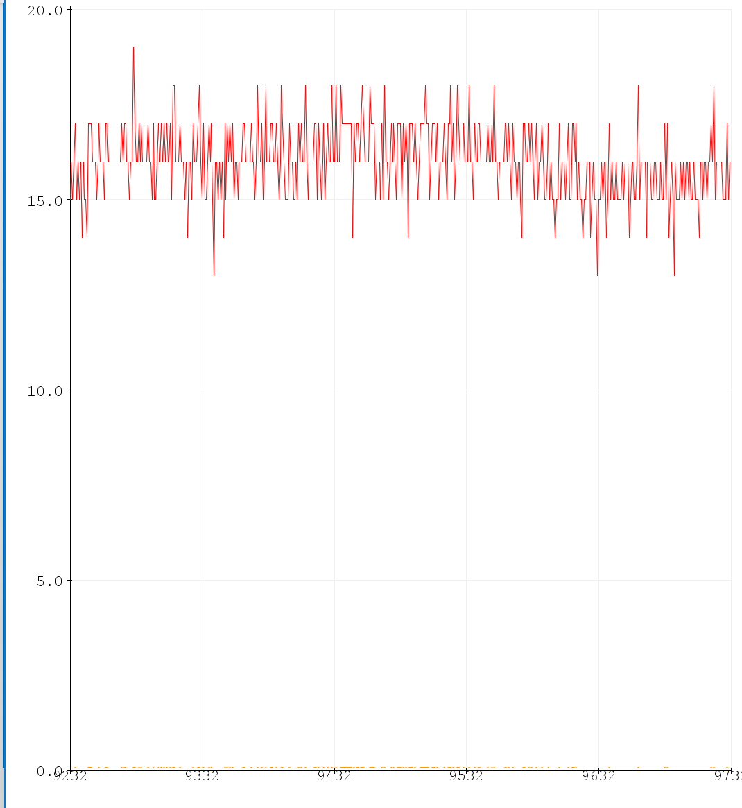
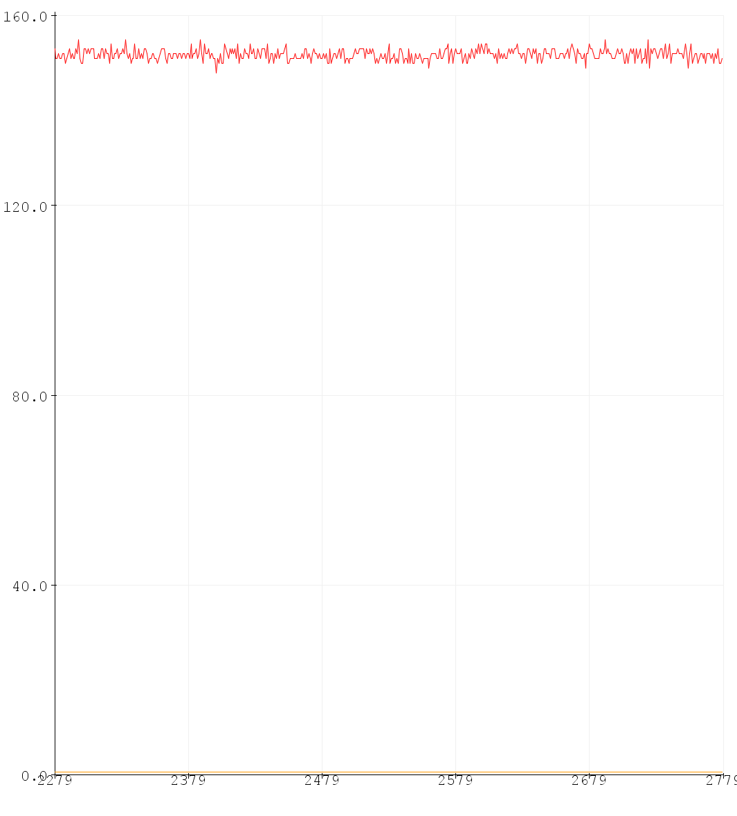
The sensor is accurate for sensing dark surfaces at short distances but underestimates distances for light surfaces and overestimates distances for far objects. Below are Serial Plotter outputs of distance in millimeters for conditions
that illustrate these trends.
Sensing 34mm away dark surface:
Sensing 34mm away light surface:
Sensing 130mm away dark surface:
Multiple Sensors:
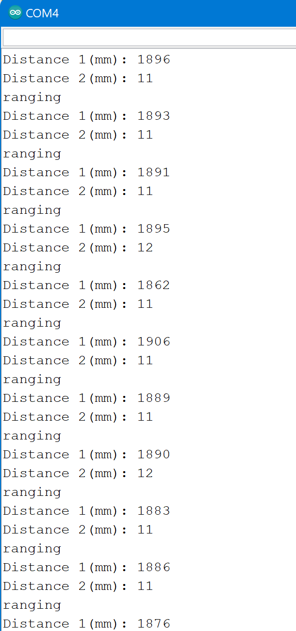
At this point I added both my IMU and second ToF sensor. I wired the XSHUT pin on my first ToF sensor to pin 8 on my Artemis so that I can shut it off while establishing a separate address for my second sensor. I then altered the ReadDistance example code to include two sensors, turning off one sensor to change the address of the other. My implementation is below, and it produced the following Serial output.
Multiple sensor code:
void setup(void)
{
    Serial.begin(115200);
    Serial.println("start");


    Wire.begin();

    Serial.println("VL53L1X Qwiic Test");

    if (distanceSensor2.begin() != 0) //Begin returns 0 on a good init
    {
      Serial.println("Sensor 2 failed to begin. Please check wiring. Freezing...");
      while (1)
        ;
    }
    Serial.println("Sensor 2 online!");

    digitalWrite(SHUTDOWN_PIN, LOW); // Shut off ToF 1
    distanceSensor2.setI2CAddress(0x22);
    digitalWrite(SHUTDOWN_PIN, HIGH); // Shut off ToF 1

    Serial.println("changed address");

    if (distanceSensor1.begin() != 0) //Begin returns 0 on a good init
    {
      Serial.println("Sensor 1 failed to begin. Please check wiring. Freezing...");
      while (1)
        ;
    }
    Serial.println("Sensor 1 online!");
  }

  void loop(void)
  {
    distanceSensor1.startRanging(); //Write configuration bytes to initiate measurement
    distanceSensor2.startRanging();
    Serial.println("ranging");
    while ( !(distanceSensor1.checkForDataReady() && distanceSensor2.checkForDataReady()) )
    {
      delay(1);
    }
    int distance1 = distanceSensor1.getDistance(); //Get the result of the measurement from sensor 1
    int distance2 = distanceSensor2.getDistance(); //Get the result of the measurement from sensor 1

    distanceSensor1.clearInterrupt();
    distanceSensor1.stopRanging();

    distanceSensor2.clearInterrupt();
    distanceSensor2.stopRanging();

    Serial.print("Distance 1(mm): ");
    Serial.print(distance1);
    Serial.println();
    Serial.print("Distance 2(mm): ");
    Serial.print(distance2);


    Serial.println();
  }
IMU Setup
ADC0_VAL:
The ADC0_VAL represents the operation mode of the microprocessor in relation to the IMU. In this case, we only want to use I2C to read from the IMU and do not need to write values to the IMU or use SPI. Therefore the ADC0_VAL should be 0
Accelerometer values:
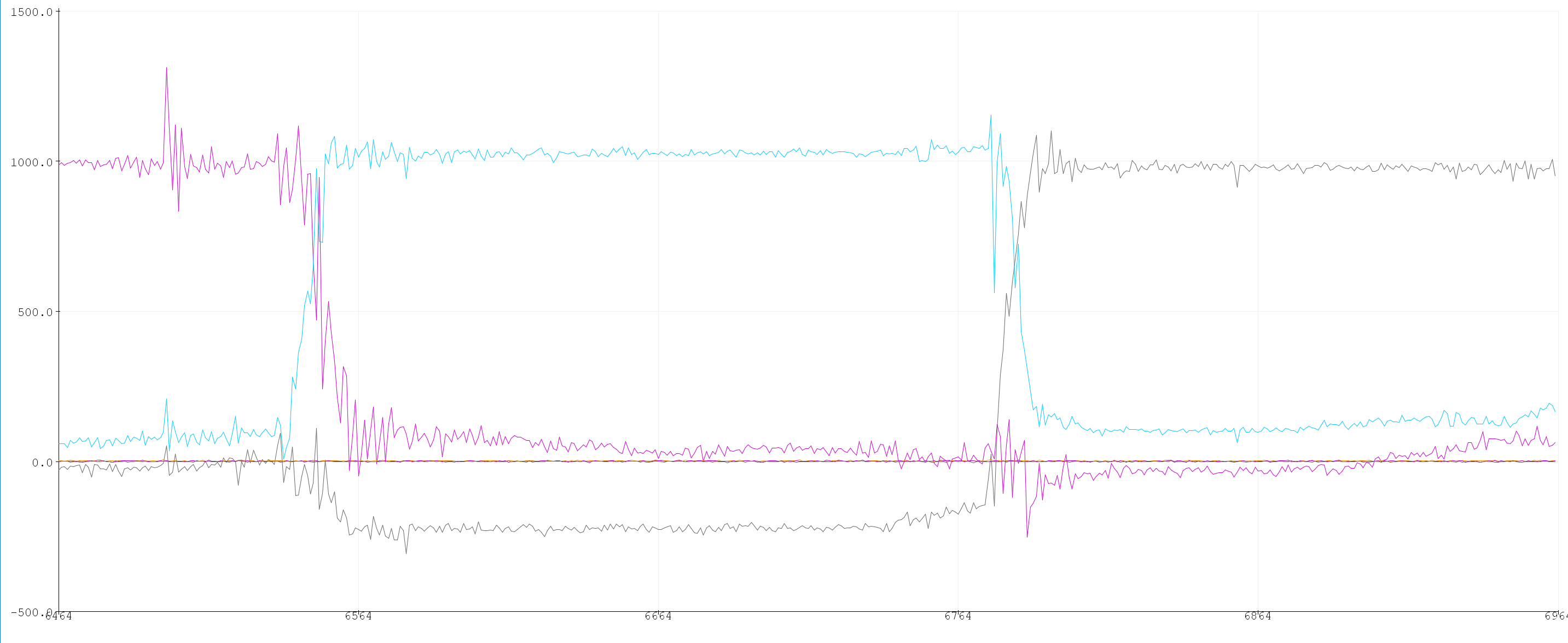
The accelerometer values are about zero for directions perpendicular to gravity and about 1000 for directions parallel to gravity due to gravitational force. The units are milli-g. The below Serial Logger plot shows the three axes of the accelerometer as I rotate the IMU over three mutually perpendicular orientations, each with one axis parallel to gravity.
Gyroscope Values:
The gyroscope values represent change in orientation along each axis. The below plot represents the same pattern of motion as with the accelerometer. The gyroscope measurements are in blue, green, and orange. They are all approximately zero except while the IMU is moving.

Accelerometer:
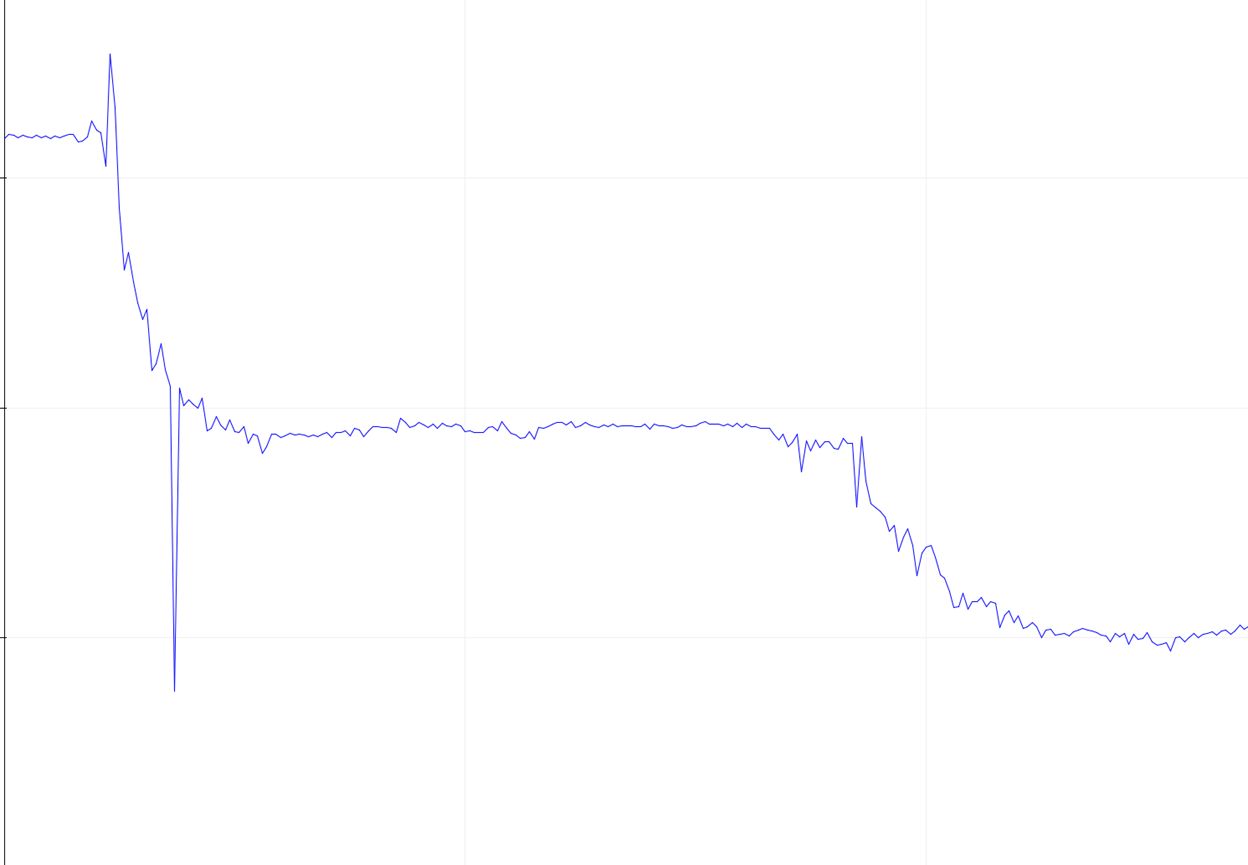
Outcome of 90deg -> 0deg -> -90deg pitch:
Outcome of 90deg -> 0deg -> -90deg roll:
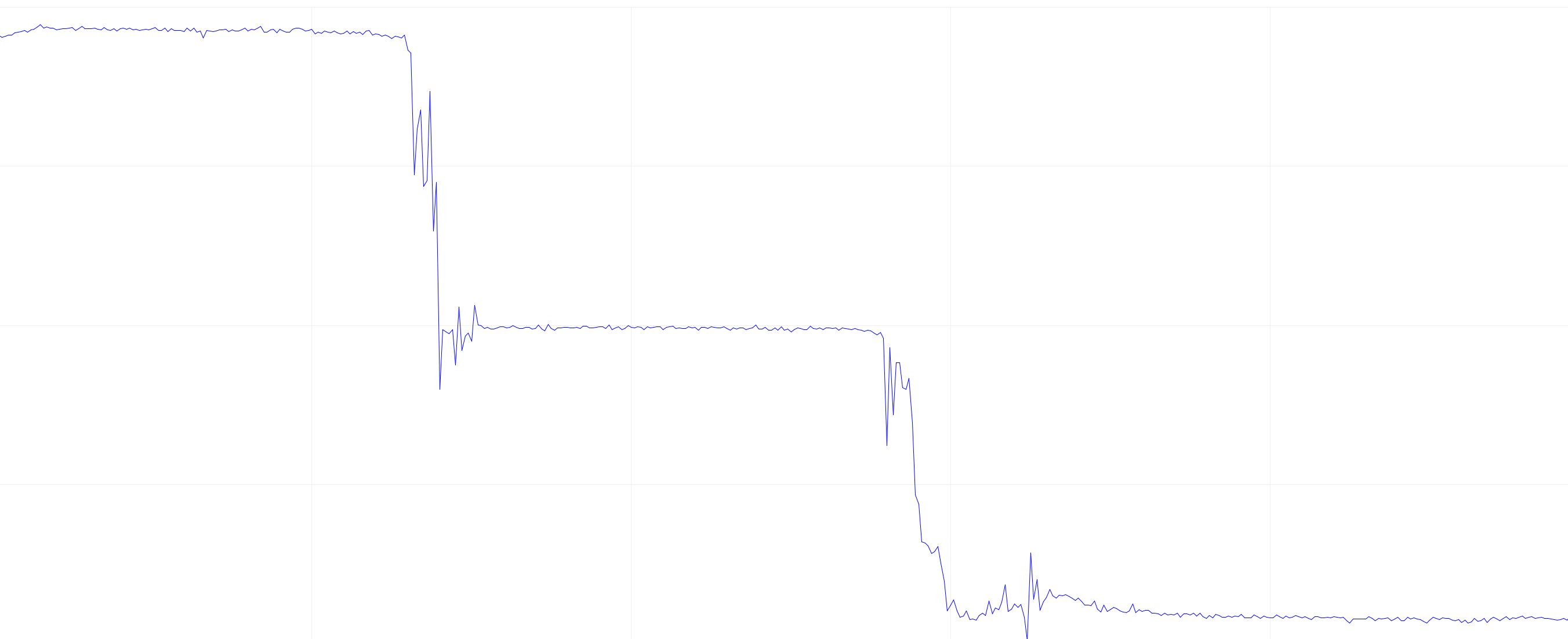
The accelerometer is accurate to within about 3 degrees.
Frequency:
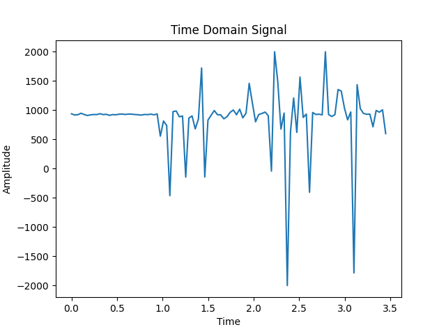
I performed an FFT with Python to get the frequency response created by tapping the IMU. The below are my outputs.
Time domain:
Frequency domain:
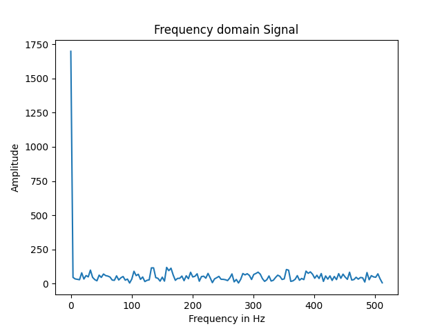
Based on this data, a low pass filter does not appear to be very necessary. If one were put in place, it would be most helpful for blocking small spikes in the 100-200Hz range, so a cut off frequency of 100Hz could be used. This limits high frequency noise that is not indicative of significant, effectual events. Instead only the general, important trends are measured.
Gyroscope:
Measurements of pitch roll and yaw from gyroscope.
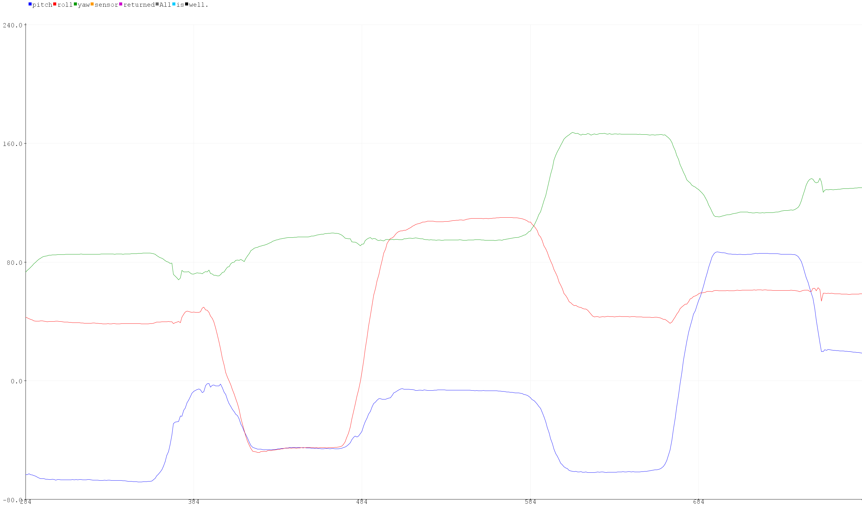
The measurements are similar to those from the accelerometer, except the gyroscope values tend to drift due to noise integration. Below is a plot demonstrating that drift.
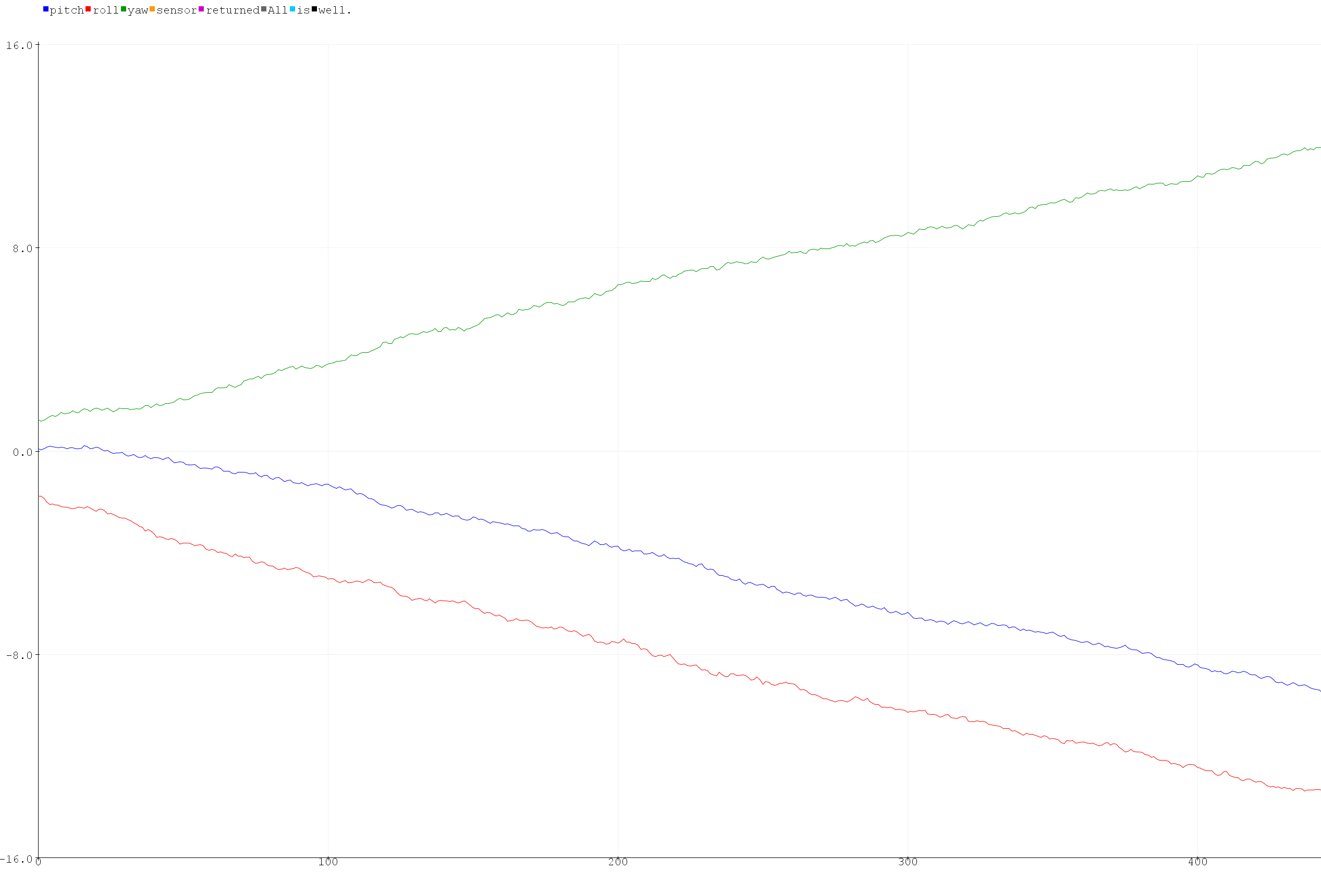
When increasing the sampling frequency the drift increases because the noise is being integrated faster.
Complimentary filter:
A complimentary filter with alpha of 0.5 yielded an accurate, if slightly noisy plot with no drift. See below plot of pitch roll and yaw while rotating.
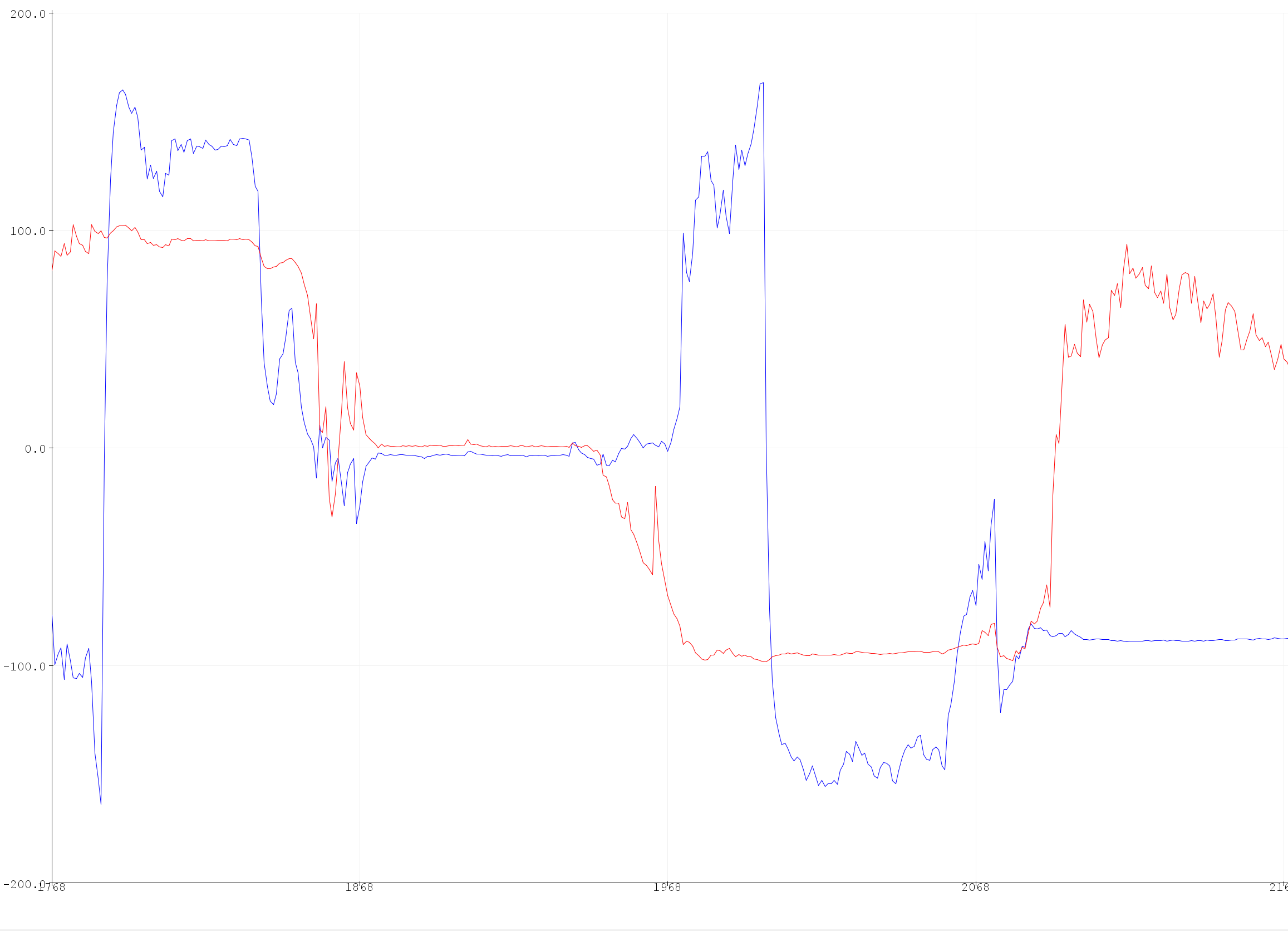
Below is the final iteration of my code, including the complimentary filter and vestiges of old functionality.
unsigned long startMillis = 0;
int count = 0;
float pitch_g = 0;
float roll_g = 0;
float yaw_g = 0;
float dt;
unsigned long last_time;

#define a .3

float complimentary_roll;
float complimentary_pitch;

void setup()
{
  SERIAL_PORT.begin(115200);
  while (!SERIAL_PORT)
  {
  };
#ifdef USE_SPI
  SPI_PORT.begin();
#else
  WIRE_PORT.begin();
  WIRE_PORT.setClock(400000);
#endif
  //myICM.enableDebugging(); // Uncomment this line to enable helpful debug messages on Serial
  bool initialized = false;
  while (!initialized)
  {
#ifdef USE_SPI
    myICM.begin(CS_PIN, SPI_PORT);
#else
    myICM.begin(WIRE_PORT, AD0_VAL);
#endif
    SERIAL_PORT.print(F("Initialization of the sensor returned: "));
    SERIAL_PORT.println(myICM.statusString());
    if (myICM.status != ICM_20948_Stat_Ok)
    {
      SERIAL_PORT.println("Trying again...");
      delay(500);
    }
    else
    {
      initialized = true;
    }
  }
  startMillis = millis();
  last_time = millis();
  count = 0;
}
void loop()
{
//  if (millis() - startMillis > 10000){ //for FFT
//    Serial.println("\nCount:");
//
//    Serial.println(count);
//    while(1);
//  }
  if (myICM.dataReady())
  {
    myICM.getAGMT();         // The values are only updated when you call 'getAGMT'
                             //    printRawAGMT( myICM.agmt );     // Uncomment this to see the raw values, taken directly from the agmt structure
    printScaledAGMT(&myICM); // This function takes into account the scale settings from when the measurement was made to calculate the values with units
    delay(30);
    count++;
  }
  else
  {
    SERIAL_PORT.println("Waiting for data");
    delay(500);
  }
}
// Below here are some helper functions to print the data nicely!
void printPaddedInt16b(int16_t val)
{
  if (val > 0)
  {
    SERIAL_PORT.print(" ");
    if (val < 10000)
    {
      SERIAL_PORT.print("0");
    }
    if (val < 1000)
    {
      SERIAL_PORT.print("0");
    }
    if (val < 100)
    {
      SERIAL_PORT.print("0");
    }
    if (val < 10)
    {
      SERIAL_PORT.print("0");
    }
  }
  else
  {
    SERIAL_PORT.print("-");
    if (abs(val) < 10000)
    {
      SERIAL_PORT.print("0");
    }
    if (abs(val) < 1000)
    {
      SERIAL_PORT.print("0");
    }
    if (abs(val) < 100)
    {
      SERIAL_PORT.print("0");
    }
    if (abs(val) < 10)
    {
      SERIAL_PORT.print("0");
    }
  }
  SERIAL_PORT.print(abs(val));
}
void printRawAGMT(ICM_20948_AGMT_t agmt)
{
  SERIAL_PORT.print("RAW. Acc [ ");
  printPaddedInt16b(agmt.acc.axes.x);
  SERIAL_PORT.print(", ");
  printPaddedInt16b(agmt.acc.axes.y);
  SERIAL_PORT.print(", ");
  printPaddedInt16b(agmt.acc.axes.z);
  SERIAL_PORT.print(" ], Gyr [ ");
  printPaddedInt16b(agmt.gyr.axes.x);
  SERIAL_PORT.print(", ");
  printPaddedInt16b(agmt.gyr.axes.y);
  SERIAL_PORT.print(", ");
  printPaddedInt16b(agmt.gyr.axes.z);
  SERIAL_PORT.print(" ], Mag [ ");
  printPaddedInt16b(agmt.mag.axes.x);
  SERIAL_PORT.print(", ");
  printPaddedInt16b(agmt.mag.axes.y);
  SERIAL_PORT.print(", ");
  printPaddedInt16b(agmt.mag.axes.z);
  SERIAL_PORT.print(" ], Tmp [ ");
  printPaddedInt16b(agmt.tmp.val);
  SERIAL_PORT.print(" ]");
  SERIAL_PORT.println();
}
void printFormattedFloat(float val, uint8_t leading, uint8_t decimals)
{
  float aval = abs(val);
  if (val < 0)
  {
    SERIAL_PORT.print("-");
  }
  else
  {
    SERIAL_PORT.print(" ");
  }
  for (uint8_t indi = 0; indi < leading; indi++)
  {
    uint32_t tenpow = 0;
    if (indi < (leading - 1))
    {
      tenpow = 1;
    }
    for (uint8_t c = 0; c < (leading - 1 - indi); c++)
    {
      tenpow *= 10;
    }
    if (aval < tenpow)
    {
      SERIAL_PORT.print("0");
    }
    else
    {
      break;
    }
  }
  if (val < 0)
  {
    SERIAL_PORT.print(-val, decimals);
  }
  else
  {
    SERIAL_PORT.print(val, decimals);
  }
}
#ifdef USE_SPI
void printScaledAGMT(ICM_20948_SPI *sensor)
{
#else
void printScaledAGMT(ICM_20948_I2C *sensor)
{
#endif
float pitch_a = atan2(sensor->accX(), sensor->accZ())*180/M_PI;
float roll_a = atan2(sensor->accY(), sensor->accZ())*180/M_PI;
//Serial.println(tilt_a);
//Serial.println(roll_a);
dt = (millis() - last_time) * 0.001;
pitch_g = pitch_g - (sensor->gyrX())*dt;
roll_g = roll_g - (sensor->gyrY())*dt;
yaw_g = yaw_g - (sensor->gyrZ())*dt;

complimentary_roll = (complimentary_roll + roll_g*dt)*(1-a) + roll_a*a;
complimentary_pitch = (complimentary_pitch + pitch_g*dt)*(1-a) + pitch_a*a;

Serial.print("pitch:");
Serial.print(complimentary_pitch);
Serial.print(", ");
Serial.print("roll:");
Serial.print(complimentary_roll);
//Serial.print(", ");
//Serial.print("yaw:");
//Serial.print(yaw_g);
Serial.println();

last_time = millis();
//  SERIAL_PORT.print("Scaled. Acc (mg) [ ");
//  printFormattedFloat(sensor->accX(), 5, 2);
//  SERIAL_PORT.print(", ");
//  printFormattedFloat(sensor->accY(), 5, 2);
//  SERIAL_PORT.print(", ");
//  printFormattedFloat(sensor->accZ(), 5, 2);
//  SERIAL_PORT.print(" ]");
//  printFormattedFloat(sensor->gyrX(), 5, 2);
//  SERIAL_PORT.print(", L");
//  printFormattedFloat(sensor->gyrY(), 5, 2);
//  SERIAL_PORT.print(", ");
//  printFormattedFloat(sensor->gyrZ(), 5, 2);
//  SERIAL_PORT.print(" ]");
//  printFormattedFloat(sensor->magX(), 5, 2);
//  SERIAL_PORT.print(", ");
//  printFormattedFloat(sensor->magY(), 5, 2);
//  SERIAL_PORT.print(", ");
//  printFormattedFloat(sensor->magZ(), 5, 2);
//  SERIAL_PORT.print(" ], Tmp (C) [ ");
//  printFormattedFloat(sensor->temp(), 5, 2);
//  SERIAL_PORT.print(" ]");
//  SERIAL_PORT.println();
}