Lab 5 - Motor Drivers and Open Loop Control:
PWM on one motor driver:
First I wired my motor driver to the power supply, using 3.3 Volts and a current cap of 10 Amps. This simulates the battery that will be used in the actual robot.
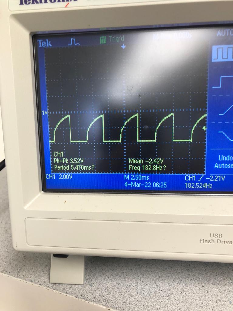
I then sent a PWM signal with 50% duty cycle to the motor driver input and measured the output with an oscilloscope. I received the below signal, which is a square wave with some capacitance. This indicates that the motor diver was working.
Wiring up motors:
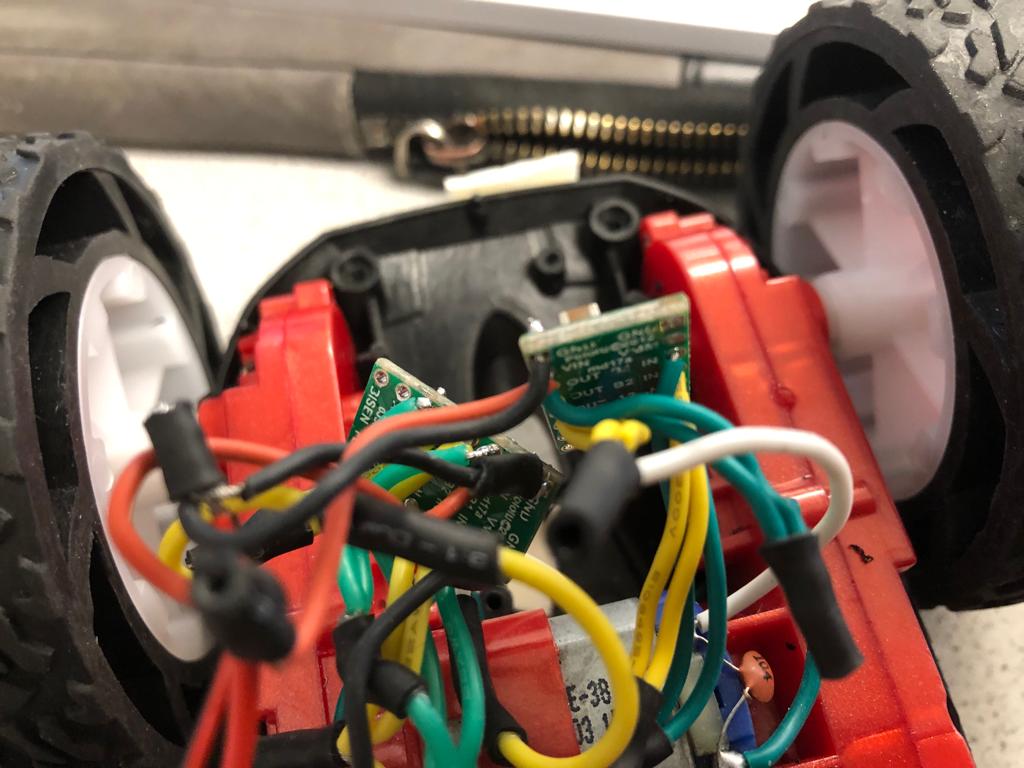
I had a lot of trouble wiring the motor drivers. I got one running, but then when I added the other one neither worked. Then I replaced both motor drivers and eventually got the car to run. Below is a picture of my motor driver wiring.
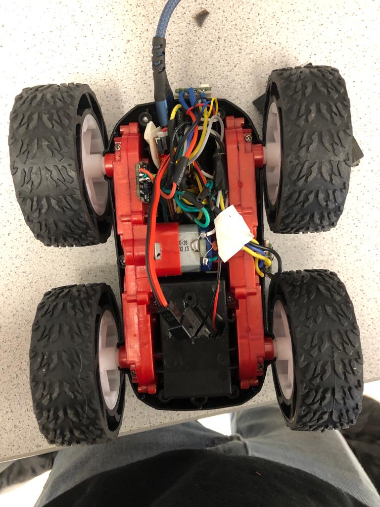
I secured all components inside the car chassis using double sided tape, and stored the batteries in the battery compartment. I drilled holes through the battery compartment to connect the batteries to my motors and microcontroller. Below is a photo of my final wiring setup.
Open Loop Control:
Below is a video of my calibrated car moving in a somewhat straight line. Given that the exact directionality of the car depends on the surface and transient physical factors, I decided that keeping it straighter than this would have to fall to control systems.
Below is a video of the car making a right turn after driving down the hallway at high speed.
Finally, I tested the ability to turn in place with the following video