Lab 6 - PID Control:
Prelab/BLE:
In order to store and analyze the robot's PID control system, my first step was to establish a system for the Artemis to communicate with another computer. This was accomplished using BLE to send commands from a lab desktop computer to the Artemis and to relay PID outputs and sensor readings back to the desktop. The reason I used a lab desktop computer instead of my laptop for this purpose is because of some Bluetooth compatibility issues with my Windows 11 laptop. My code for this communication is as follows:
C++ code to send data:
void write_data(){
  Serial.println("Write data");
  for (int i=0; i<ARR_SIZE; i++)tx_characteristic_float.writeValue(front_tof_readings[i]*1.0);
  for (int i=0; i<ARR_SIZE; i++)tx_characteristic_float.writeValue(times[i]*1.0);
  for (int i=0; i<ARR_SIZE; i++)tx_characteristic_float.writeValue(motor_pcnts[i]);
}
Python code to receive data:
    def pid_data_callback_handler(self, uuid, byte_arr):
            # Append a tuple (value, time) to a list
            fl = ble.bytearray_to_float(byte_arr)
            # print(str(fl))
            if len(self.data_list[self.feature_ind]) < self.ARR_SIZE:
                self.data_list[self.feature_ind].append(fl)
            elif self.feature_ind < len(self.feature_names_list)-1:
                self.feature_ind = self.feature_ind + 1
                self.data_list[self.feature_ind].append(fl)
            else: print("unexpected data")

            if self.feature_ind == len(self.feature_names_list)-1 and len(self.data_list[self.feature_ind]) == self.ARR_SIZE - 1:
                print("done recieving")
Because the sizes of the PID output arrays are constant parameters that I decide, I chose to have my Python code utilize knowledge of the data array sizes in order to simplify transmission. Once PID operation is complete, the Artemis simply sends all float data representing the TOF sensor data, time stamps, and motor inputs in that order using the TX float characteristic from Lab 2. The Python notification handler keeps track of what data has already been received and stores incoming data accordingly.
PID Control:
Next up is to actually implement the PID control in order to complete a task and obtain data in the process. I decided to implement task A, which was to stop 300mm away from a wall. The intended behavior was to send a command over BLE to the robot, which would then execute PID until its data arrays were full, at which point the car stops entirely and sends diagnostic data back to the desktop in the manner described above. This was implemented with the following code:
Outer loop logic:
            if (do_PID){
            if(sensor_data_ready() && measure_count < ARR_SIZE){
                //Doing PID and just got new sensor reading
                curr_mil = millis();
                new_tof = get_front_tof();
                pcnt = pid(measure_count, curr_mil, new_tof);

                move_speed(pcnt);
                store_data(measure_count, curr_mil, new_tof, pcnt);
                measure_count ++;

              }
              else if (measure_count >= ARR_SIZE){
                active_stop();
                write_data();
                do_PID = false;
              }
            }
PID function:
float pid(int index, long time_stamp, int tof_dist){
  int error = tof_dist - TARGET_DIST;

  float deriv;
  if (index == 0){
    deriv = 0;
    integrator = 0;
  }
  else{
    int dt = time_stamp - times[index-1];
    deriv = (tof_dist - front_tof_readings[index-1]) / dt;
    integrator = integrator + dt*error;
  }
  float raw = KP * error + KI * integrator + KD * deriv;
  if (raw > 100) return 100;
  if (raw < -100) return -100;
  return raw;
}
Tuning PID:
At first, I tried using only a P controller and set my KI and KD parameters to zero. However, even with small KP I was getting a significant amount of overshoot due to slow sensor readings and an inability to slow down sufficiently. This led to the robot
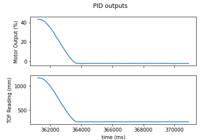
hitting the wall on several trials. I added a non-zero KD term to the controller which succeeded in dampening the output. Below is a video of my most successful trial using a PD controller, and graphs of the sensor readings and motor inputs
used. The motor inputs are percentages which are scaled into PWM values using the scaling function
PWM = 20 + 0.85 * pcnt
This avoids the deadband and gives a max PWM input of 105.
Video of PD Control for Task A:
Plots of PD Control outputs for Task A:
